|
It’s very interesting to look at the place the handplane occupies in the history of woodworking. One of the most important changes that occurred in this history was the progression from the carpenter - whose main tools were the axe, adze and saw - to the joiner, cabinet maker and other craftsmen, all of whom needed components produced to precise dimensions and a smooth finish. It was the handplane alone that made this development possible.
Prior to the machine era this important preparatory work was done by hand with bench planes. The introduction of machinery and power tools dramatically reduced both the labour component and the time requirement. These benefits are unquestionably essential in today’s commercial workshops, so it is therefore inevitable that the bench plane would become far less important. Despite this, the simple truth remains that a plane works better and more efficiently than a machine in many situations.
For example, no machine with rotating blades can match the clarity and polish produced on a surface cut with a well tuned and sharp handplane. Surface ripples left by some thicknessing machines are best removed with a bench plane. When fitting a joint such as a mortise and tenon, no tool is more useful than a shoulder plane. The difference between a well fitted drawer and a loose one is often a little more than a thin plane shaving. A plane allows you to do this, one shaving at a time. What machine can do that? Similarly, the fitting of a door and cabinet is most easily and accurately done with a bench plane. Cleaning up after having glued up a joint with dovetails or finger joints is quickly and neatly done with a block or bench plane.
There are numerous other situations in which a handplane is the most appropriate tool. Possibly the most important reason for learning to use one is that the skills you acquire can transform the standard of your craftsmanship. It is not a difficult tool to use, like swimming or riding a bike, it’s never forgotten. Many of the older generation of craftsmen - those who spent their early years working only with hand tools - find these skills of great benefit when using machinery.
Frank Klaus, the highly regarded European craftsman, now based in America, states that once mastered, the handplane becomes the most important tool in your workshop. James Krenov, regarded by many as the most influential craftsman in fine woodworking in the last 30 years, likens the plane to the violin in an orchestra, the instrument that sets the tone of a piece. If that’s not enough, planes, properly used, can make your woodworking more enjoyable. Certainly, your workshop becomes a quieter and cleaner place.
In short, there is no substitute for a well sharpened and finely tuned handplane.
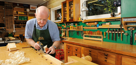
Peter Geddes is a Brisbane-based woodworker. He teaches classes in handplane usage entitled ‘Making Friends With Your Handplane' at Carbatec® in Brisbane.
Some of Peter's top tips for using your handplane
Bench height
Bench height is important. You need to be able to apply appropriate downward pressure as you push the plane forward. A high bench restricts you to using the weaker muscles in your arms, your plane strokes are jerky and hesitant and you tire quickly. A lower bench, on the other hand, enables you to use your torso and leg muscles, thereby allowing you to work more comfortably for much longer without tiring. Most benches are about 34 ½ inches, which is possibly an inch or so too high for shorter woodworkers and too low for the six footers. Try experimenting with the height of your bench. Getting it right can make a significant difference.
Skewing the plane
Skewing, or holding the plane at an angle to the direction of the stroke, feels natural and has important advantages. It lowers the cutting angle, thereby making the plane easier to start and to push and provides an additional slicing action. However, there is also an important disadvantage - when working wood that is inclined to tear out, particularly where the grain rises quickly, skewing will worsen the problem. The answer is to straighten the plane in those spots that tear out, or even reverse it. Skew the plane only to the extent that you can keep the entire length of the sole supported on the workpiece. This means it is rarely more than 30 degrees. Right handers skew to the left and vice versa.
Waxing the sole
Steel planes don’t slide over wood as smoothly and easily as wooden ones. Rubbing the sole of your steel plane with candle wax (a couple of strokes only) dramatically reduces the friction. If you have a lot of planing to do, then an ‘oil wick’ is a better method. It consists of a rolled up piece of felt standing up on edge in a jar or inserted in a block of wood. A small quantity of linseed oil is applied to the wick which is placed so that you can drag the plane’s sole over it on the return stroke. Be very sparing on the oil. It is most difficult to apply some finishes over oily wood.
Sharpening
Most woodworkers appreciate the importance of a sharp blade. The subject of sharpening is large and beyond the scope of a list of tips. However, it is regarded as “good practice” to stop frequently and freshen up the blade, particularly when using a smoothing plane. It is better to keep the blade as sharp as possible, rather than struggle on with a half blunt one and risk, amongst other things, tear out. Many a project has been delayed by unwanted tear out in the final stages. If you have your sharpening stones nearby and ready to use, then it is entirely possible to stop, touch up the blade and be back at work within two minutes.
Take a look at Carbatec's range of handplanes here.
|